Vehicle Tracking in Civil 3D: Install and Swept Paths
Autodesk’s BIM software, Civil 3D, provides users with various add-ins that help improve model design by providing additional information and analysis. A clear example is the “Vehicle Tracking” add-in, which makes it possible to simulate the movement of different vehicles, analyze swept paths during turns, and more. It also includes tools for designing roundabouts, intersections, and parking areas.

DOWNLOAD AND INSTALLATION
If the add-in is not already installed with our software, it can be downloaded from the official Autodesk website.
MENUS - TOOLS
- SETTINGS:
This is one of the first menus we should open before starting to use the add-in. When accessing this tab, a window opens where we can configure the scale in relation to the model, distance, speed and angular units, layer criteria, turning restrictions, forward and reverse speeds, and more. Although Civil 3D includes rules and configurations for each country, it is worth taking some time initially to review this menu and configure the different parameters according to the requirements of our project. Note: These settings are general and apply to the entire project.
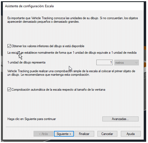
Although Civil 3D includes rules and configurations for each country, it is worth taking some time initially to review this menu and configure the different parameters according to the requirements of our project. Note: These settings are general and apply to the entire project.
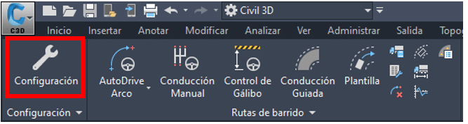
- SWEPT PATHS: This group contains several tools for creating vehicle paths. For this short demonstration, we will use the AutoDrive tool, which is the easiest and most automated option for generating a vehicle path using the default settings, which, as mentioned above, can be customized.
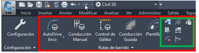
We can also generate reports and insert charts and profiles. - PARKING AND ROUNDABOUTS: These tools can be used to design roundabouts and parking areas in accordance with the regulations of the corresponding country.

- REVIEW – ANIMATIONS – HELP: Among these final tools, one of the most notable features is the ability to generate visual animations, both schematically in plan view, displaying the swept path lines, and in 3D.

CREATING PATHS WITH AUTODRIVE
The process of creating and simulating paths with the “AutoDrive” tool is simple and intuitive. When this option is selected, a menu opens where we can define specific settings for the particular path we are going to generate. Two of the most important aspects to consider are: 1. SURFACE: First of all, we need to understand that Vehicle Tracking performs these simulations on a reference plane or surface. Either in the general settings tab or in the specific settings for each path, we must specify the reference surface on which the simulation will be performed. 2. VEHICLE SELECTION: Vehicle Tracking contains an extensive library of vehicles classified by category, country, and other criteria. We select the vehicle that best suits the analysis to be carried out. If the desired vehicle is not available, it is possible to configure one of the existing vehicles in the library.
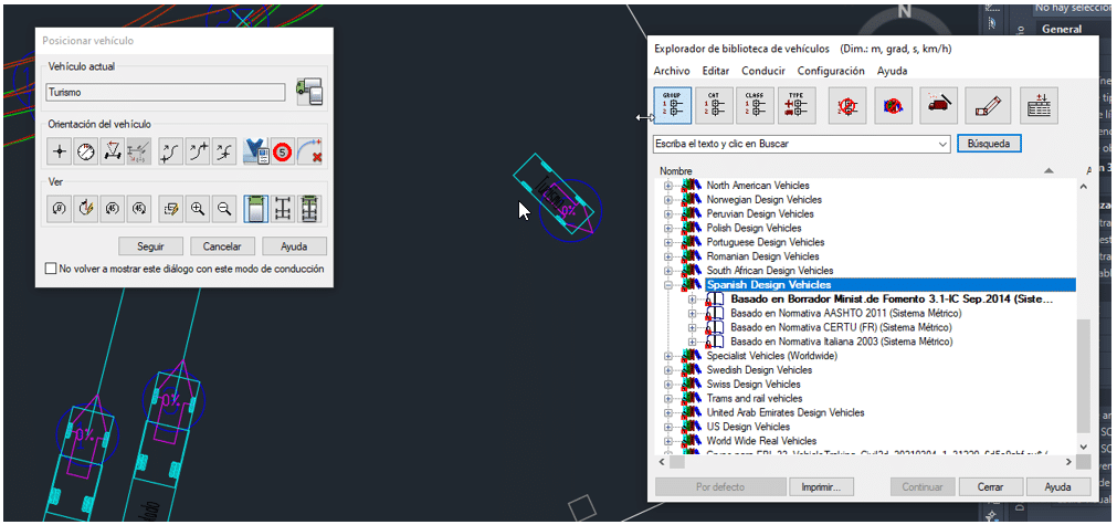
Once all the preliminary settings have been configured, we can create the vehicle path. It can be drawn freely or assigned to an alignment that the vehicle will follow. At the end of this post, we provide a simple demonstration of how to use this tool.
ANIMATION AND SIMULATION
Once the paths have been created, we can select those we want to combine within the same simulation. The tool allows us to generate different types of simulations: in plan view (displaying the swept path lines), in 3D, and more, while configuring them according to our requirements. It also allows us to save these simulations as “viewpoints”, videos (AVI format), and other formats.
For a complete step-by-step case, from preparing the surface to setting up the vehicle and creating the animation, follow the Vehicle Tracking AutoDrive tutorial.