Vehicle Tracking Tutorial: AutoDrive in Civil 3D
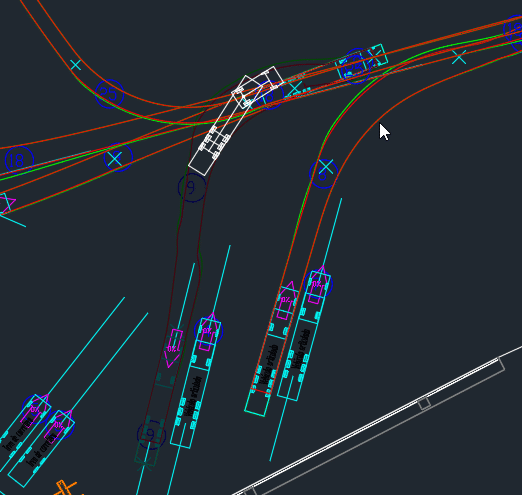
OBJECTIVES
- Review and expand on the information from the first post about Vehicle Tracking.
- Learn how to create simulation paths for vehicle movements and turns.
- Gain a general understanding of the tools and configuration options offered by the add-in.
- Learn how to generate animations.
REQUIREMENTS
- Use Civil 3D 2018 or later.
- The user must have the Vehicle Tracking add-in correctly installed.
- Basic knowledge of Civil 3D or AutoCAD (creating surfaces, creating and editing layers, etc.).
CONFIGURATION
- Install Civil 3D using the default settings.
- Install the Vehicle Tracking add-in.
PROCEDURE
1. PREPARING THE ANALYSIS AREA (CREATING A SURFACE / CORRIDOR)
Open the project file on which the analysis will be performed. It must contain a surface or corridor on which the add-in can draw the vehicle paths and swept paths.
2. GENERAL SETTINGS
Once the model on which the analysis will be performed is ready, go to the “Vehicle Tracking” tab that appears in the toolbar after installing the add-in. Then access the general settings menu.

In this menu, we can modify the settings that will be applied to all vehicle paths drawn in that file or model.
- Scale
- Units
- Layers
- Turn transitions
- Design speed
- Steering limits
- Articulation limits
- Dynamics
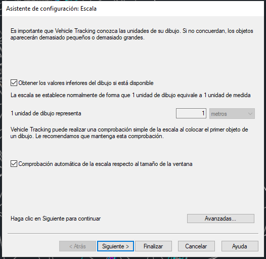
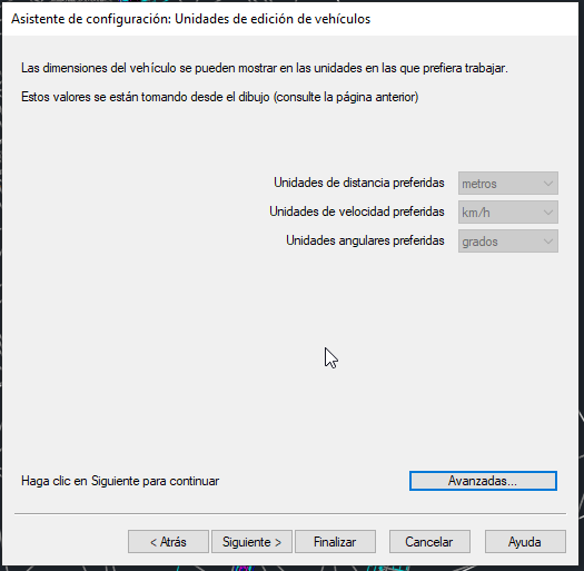
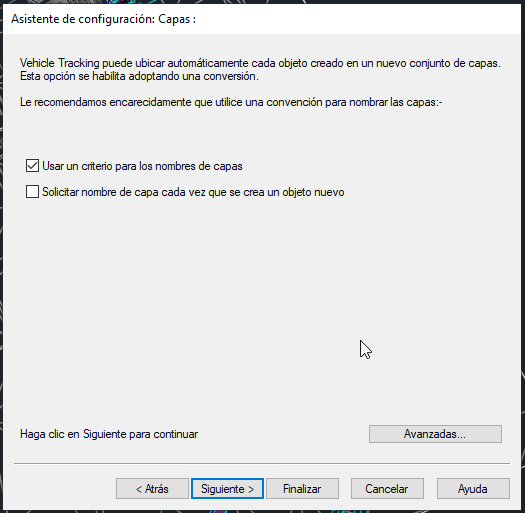
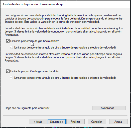
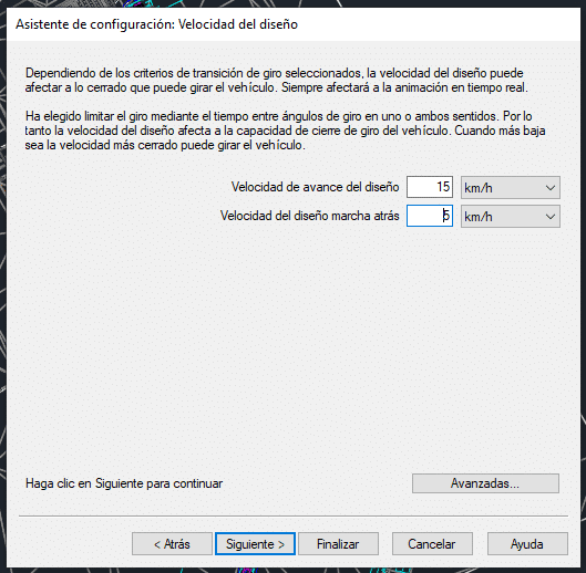
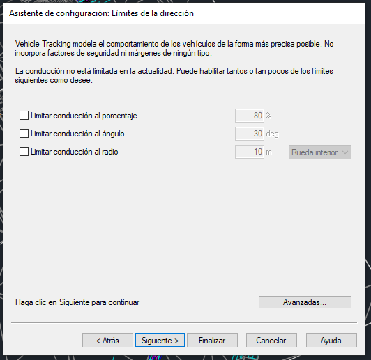
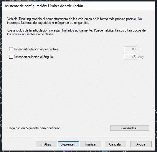
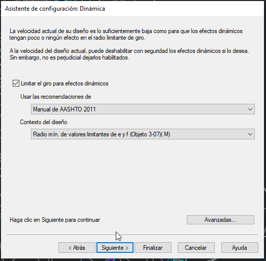
For our example, we kept the default settings, changing only the forward and reverse speeds to 15 km/h and 5 km/h respectively.
From this menu, we can also access the advanced settings, among which the following are particularly useful:
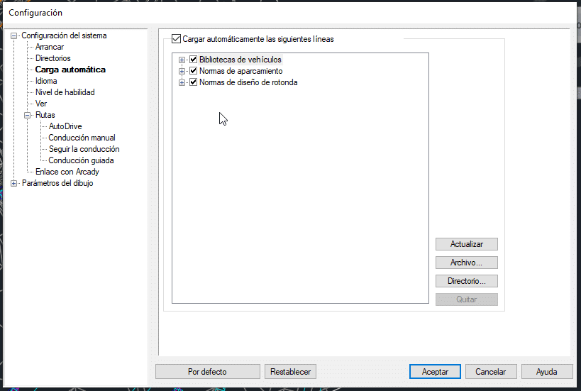
- Automatic loading: Displays the libraries and standards loaded by default. It also allows them to be updated, new ones to be added, etc.
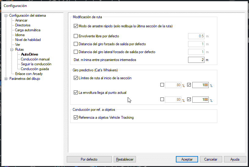
- AutoDrive:
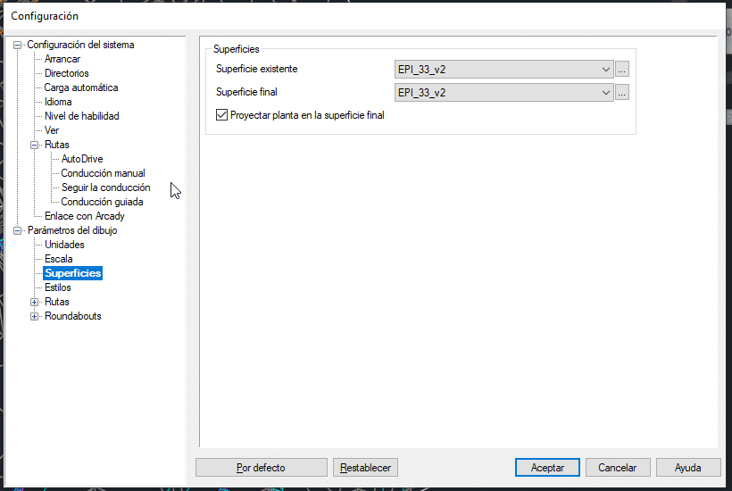
- Surfaces: Allows you to select the surface on which the vehicle path will be drawn.
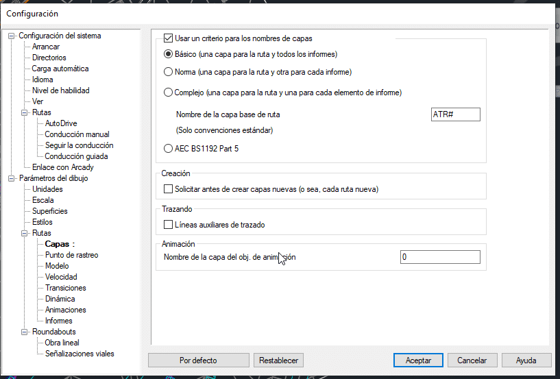
- Layers: Configures how the elements generated with Vehicle Tracking are created and managed within layers.
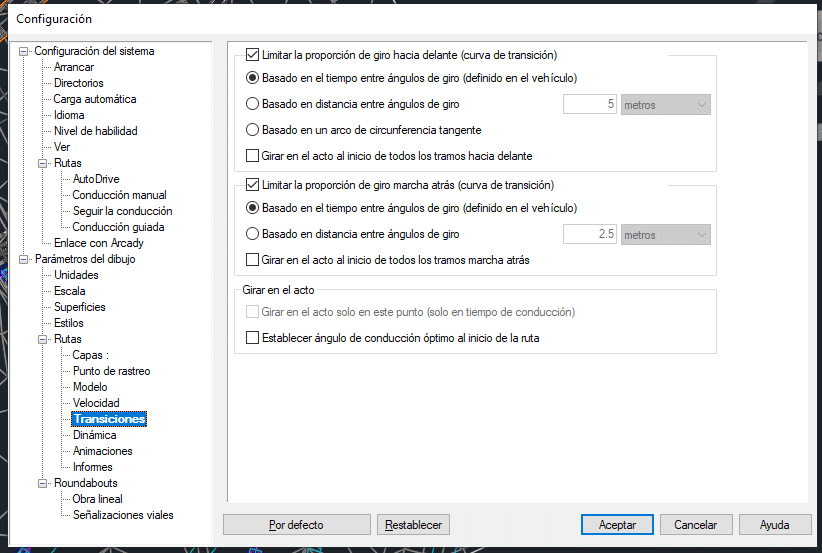
- Transitions: (Turn ratio)
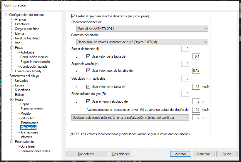
- Dynamics:
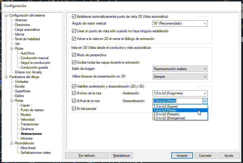
- Animations: Among other settings, we can specify acceleration and deceleration (gentle, firm, heavy, or emergency).
- Reports: These “reports” are displayed visually along the path assigned to the vehicle. They allow us to configure which markings are displayed on the vehicle path or swept path (e.g. drag lines, invalid path, annotations, chassis outline, etc.).
3. AUTODRIVE
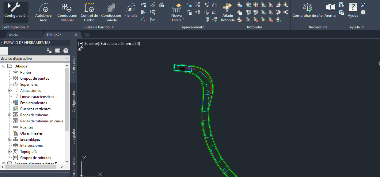
Unless a very specific analysis is required or we want to adjust the vehicle path with greater control and precision, the most convenient tool for defining the vehicle route is “AutoDrive Arc”.
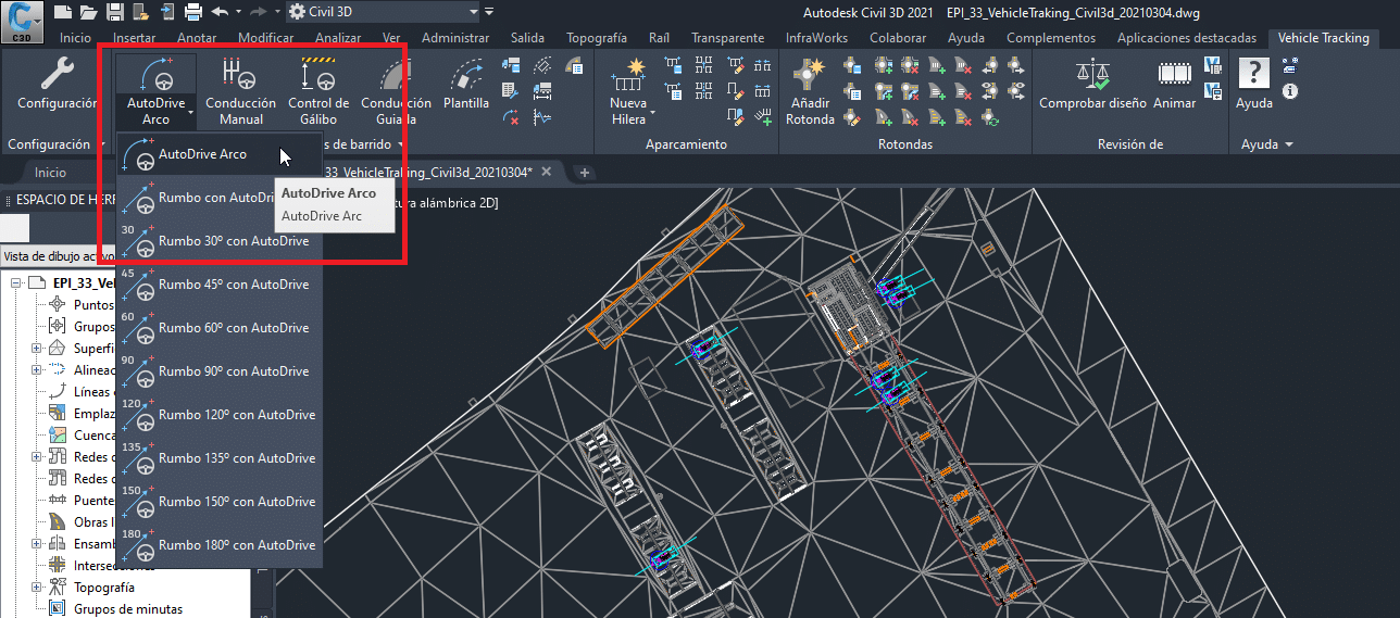
Once this tool is launched, a window opens from which we can access the various settings mentioned above and modify them specifically for the route we are generating.
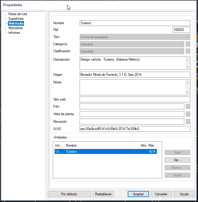
One of the most useful menus is the “Vehicle Library Explorer”. It contains an extensive library of vehicles classified by country, type, category, etc.
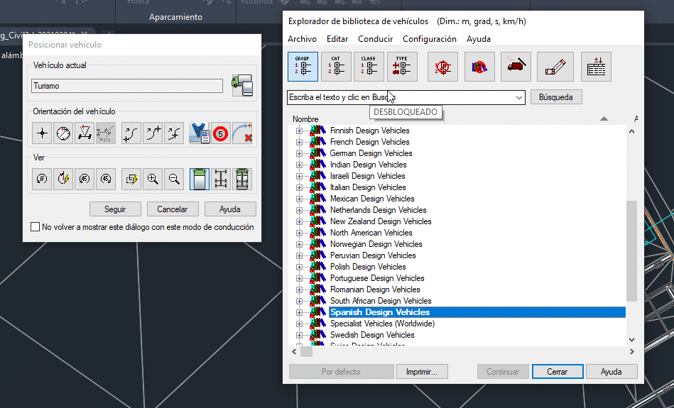
From these windows, we can choose the vehicle that best suits the requirements of our analysis or edit an existing one to create a new vehicle type with the desired characteristics.
Example: Spanish Design Vehicles -> Based on Ministry of Public Works Draft -> Van.
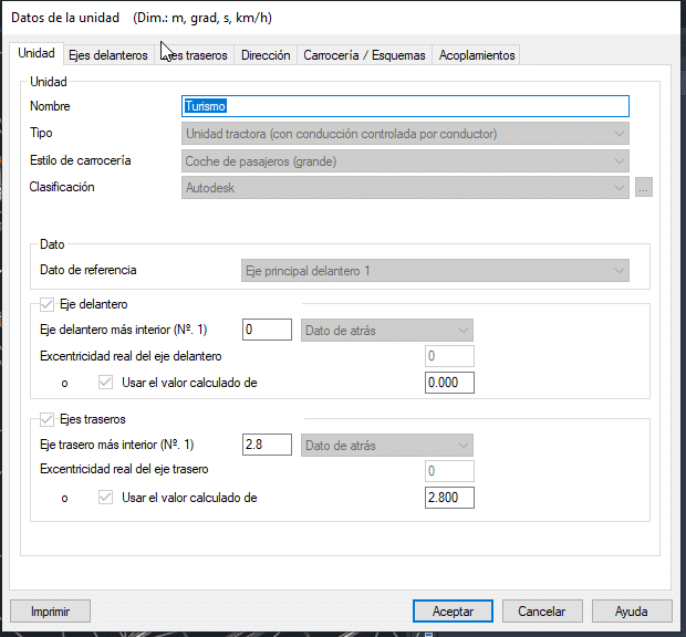
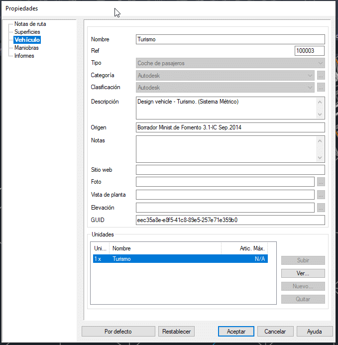
Once the vehicle has been selected and configured, we position it within the study area (surface or corridor), specify its orientation, and begin drawing its route. Depending on the established settings, the program will limit the turning radii according to speed, display the swept area, and so on.
4. CHECKING AND ANIMATIONS
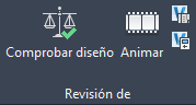
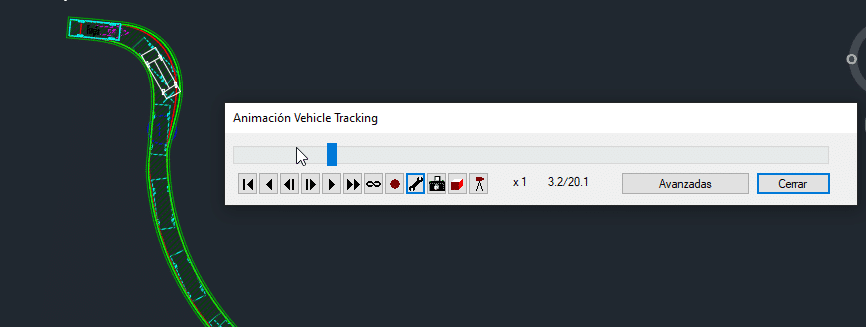
Finally, once the route has been generated, the program allows us to check the design by displaying irregularities or non-compliances, rollover risk warnings, and other issues. We can also access the “Animate” menu, where the vehicle movement can be viewed both in plan and in 3D.
Among the options available in the animation window, the most notable are the playback controls, the record button, the settings button (for editing acceleration/deceleration, etc.), as well as the snapshot, 3D, and ground-level camera options.
We will be happy to help if you need any further information, so please do not hesitate to contact us at info@atbim.es