Introduction to Using Dynamo in Civil 3D
1. Introduction
As part of our efforts to promote BIM workflows and the advantages and opportunities they offer, today we would like to introduce you, through this short post, to the use of tools such as Dynamo for Civil 3D.
Autodesk Dynamo for Civil 3D is a visual programming application that can be used to automate tasks in Civil 3D. Once the application is installed, Dynamo commands are available in the Manage ribbon.

We have already discussed Dynamo for Revit on other occasions and, as you will see, the graphical environment and the way it works are identical. Although the number of nodes developed for Civil 3D is much smaller than those available for Revit, we can still access some very useful nodes for optimizing our workflow.
In future posts, we will look at several examples using predefined nodes as well as others developed by our team through Python scripts.
The main difference we can identify in the graphical environment is the new Civil 3D section that appears in the “Library” area.
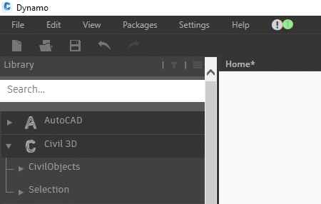
From this section, we have access to the different nodes that can be applied to specific elements of our Civil 3D model:
- Alignments
- Profiles
- Corridors
- Surfaces
- Subassemblies
- …
The next step, just as in Revit, is to create our own definitions according to our needs by combining and interconnecting the different nodes.
We can also search for packages created by other users or share our own.
2. Practical example
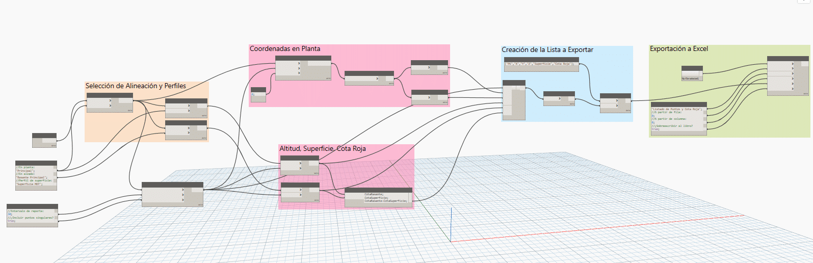
As an example of automation, we show this simple but useful Dynamo workflow, which allows us to extract the coordinates of an alignment into an Excel spreadsheet:
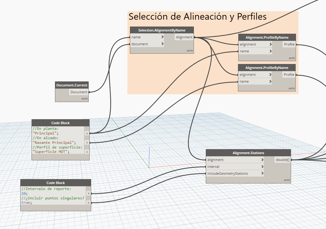
Using the following nodes, we specify the file from which we want to extract the data, as well as the names of the alignment and profiles (alignment and surface profiles). The lower node specifies the tracking or data extraction intervals (every 20 meters in this case).
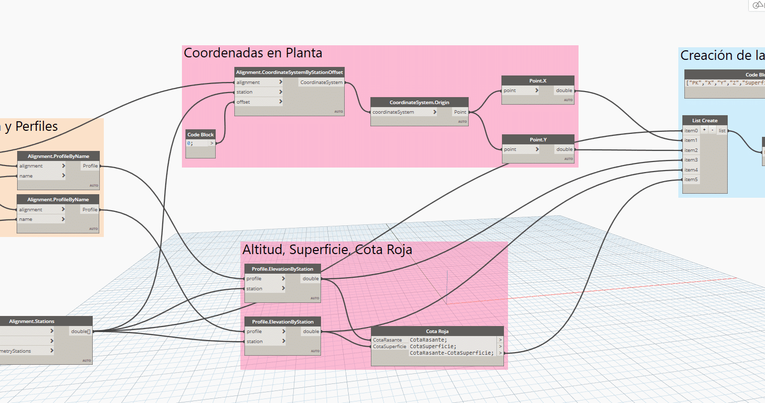
The next step is to specify the data to be extracted: plan coordinates and surface and alignment elevations at the established intervals. In addition, we want to include one more parameter: the cut/fill height.
Since there is no specific node for obtaining this value, we designed a simple script that performs the following operation using the elevation data to obtain the cut/fill height:
{CUT/FILL HEIGHT = DESIGN GRADE ELEVATION – SURFACE ELEVATION}
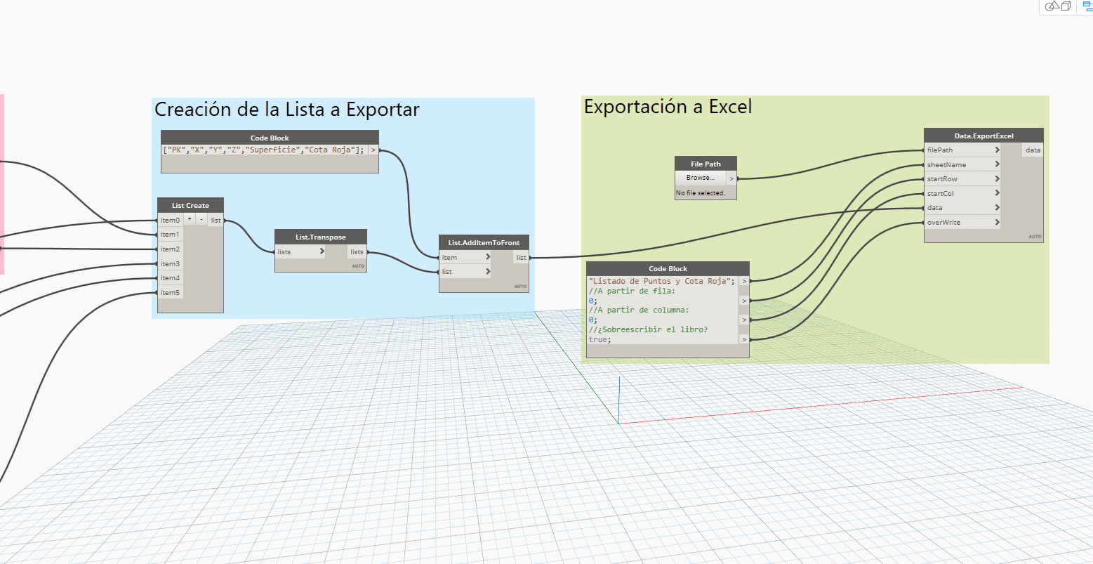
Finally, all that remains is to create a list containing the data obtained (List Create) and export it to an Excel file (Data.ExportExcel).
For more information, please do not hesitate to contact us at info@atbim.es
By Ignacio Orús, BIM Specialist at ATBIM.