BIM Reinforcement Modeling: Wind Turbine Foundation Structure
We often read posts, blogs, and articles about reinforcement modeling, but very few focus on structural elements with unconventional shapes. At ATBIM, we regularly work on BIM wind turbine projects, and in this post we explain a particular case. It involves an isolated foundation where we will explain the techniques used to model reinforcement for any type of foundation, eliminating the misconception that this cannot be done with Revit.
“Unconventional” shapes in Revit need to be handled differently when creating reinforcement compared with the standard approach we are used to by default. Although internally the process is essentially the same for the software, we need to consider the geometry from a holistic perspective and study it thoroughly from different points of view.
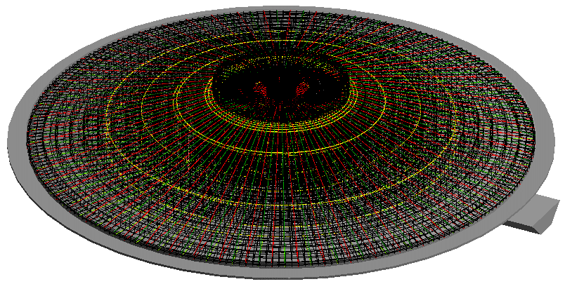
3D view of the complete circular foundation
In this particular case, the foundation has the shape of a pyramidal cone, with blinding concrete and a rectangular base to accommodate the required service conduits.
First, the parametric foundation family was created (we consider this process to be relatively straightforward for an intermediate Revit user), followed by its reinforcement.
How is this type of reinforcement modeled in Revit?
At first, we might think that it can be modeled in the same way as a conventional foundation, but this is not actually the case. Revit has significant difficulties interpreting “hosts” that are not cubes or straight-edged shapes. Therefore, in this case, the reinforcement shape must be created manually using “Sketch Rebar”. Although this may initially give the impression that more work is required, in practice this is not the case.
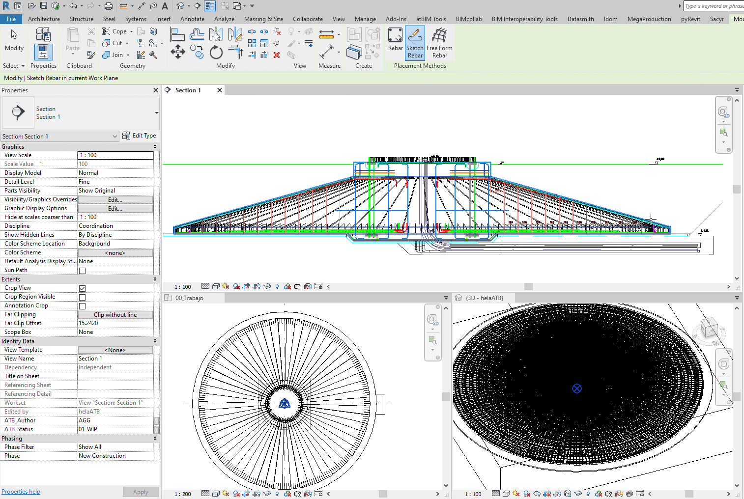
Tiled view for reinforcement modeling
By learning to work with tiled views (section, plan, and 3D views), the amount of work and effort can be significantly reduced, as the user can quickly move between all the different views.
The most important step is to understand that all the different reinforcement shapes will be modeled in section. From there, the circular arrangement is created using arrays, taking into account symmetries and possible similarities. In this particular case, the foundation is symmetrical across its quadrants.
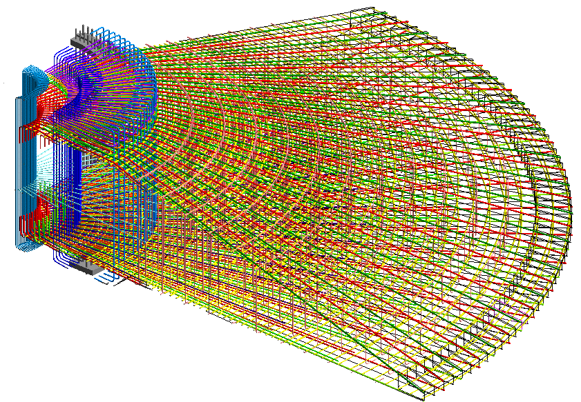
3D view of one of the symmetrical quadrants
To complete the work and make effective use of the reinforcement tool, the visibility options must be configured and adjusted. By default, it should be taken into account that reinforcement is only visible in the views in which it is modeled, helping to prevent the model from becoming excessively heavy. For this reason, specific 3D views were created to apply dedicated filters and visibility settings. In this case, we generally work with bar numbering, using a specific parameter applied to structural rebar so that the elements can be filtered.
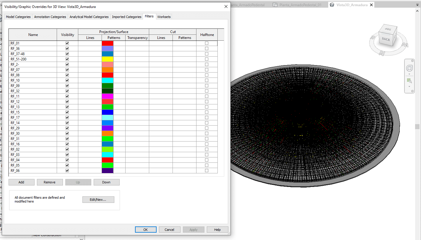
3D view and filters generated by numbering type
In the following posts, we will continue explaining the process, including how a Dynamo definition was created to automatically modify the dimensions based on data from Excel.
If you have any questions, please do not hesitate to contact us: info@atbim.es
By Andrea Gracia, BIM Coordinator at ATBIM.