BIM Modeling of Reinforcement: Footing Structure for Wind Turbines
We usually read posts, blogs and articles where reinforcement modeling is discussed, but none focused on structural elements that do not have common shapes. At ATBIM we work on BIM Wind Turbine projects regularly and in this post we explain a peculiar case. It is an isolated footing where we will explain the techniques to model reinforcement, for any type of footing. Eliminating the misconception that it cannot be done with Revit.
“atypical” shapes in Revit need to be treated differently when assembling than what we are used to by default. Although fundamentally and internally for the program it is the same, we must consider its geometry from a holistic point of view and study it in depth from different points of view.
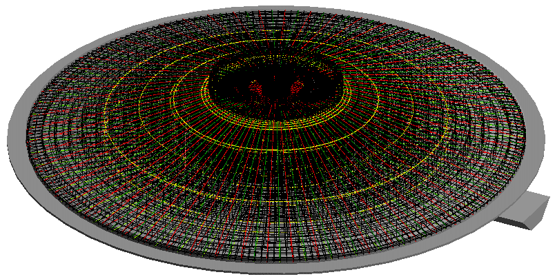
3D of the complete circular shoe
In this specific case, it is a footing in the shape of a pyramidal cone. With cleaning concrete and rectangular base to accommodate the necessary pipes.
First, the parametric foundation family has been generated (we consider this to be of little interest to a medium-level Revit user). And, then, their armor.
How are these types of reinforcements modeled in Revit?
At first we may think that it is in the same way as a conventional shoe, but the truth is that it is not. Revit has major problems understanding “hosts” that are not cubes or straight shapes. Therefore, and in this case, the shape of the reinforcement must be created manually using “Sketch Rebar”. Although this at first may give the wrong idea of more work, the truth is that this is not the case.
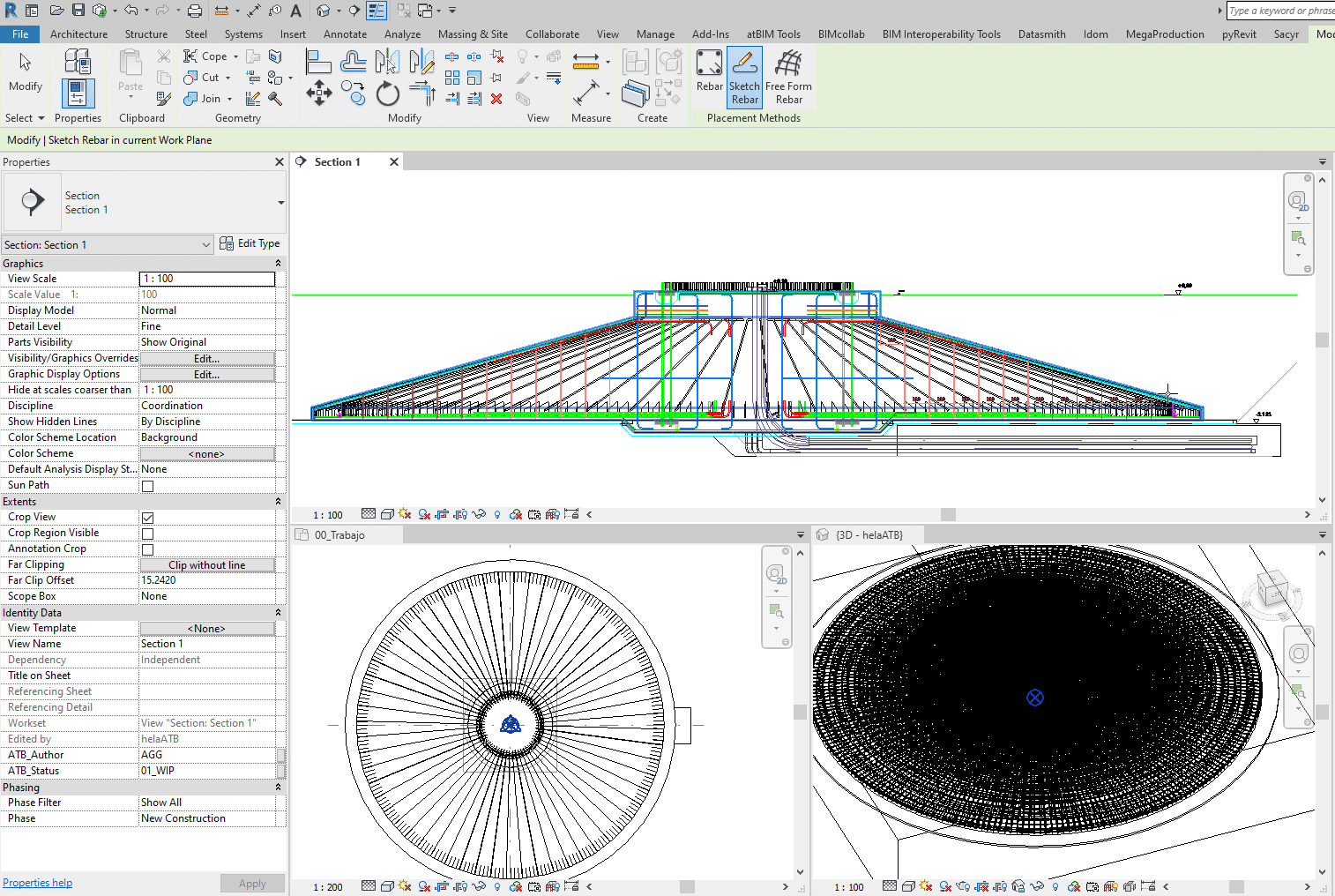
Tile view for modeling armor
If you learn to work with mosaic views (section, plan and 3D views), all the work and effort is reduced by half, since the user will be able to move freely through all the views quickly.
The most important step is to have the idea that all the different shapes of reinforcements will be molded in section. And from there, the circular shape will be made using matrices, taking into account symmetries and possible similarities. In this specific case, it is a footing, symmetrical in quadrants.
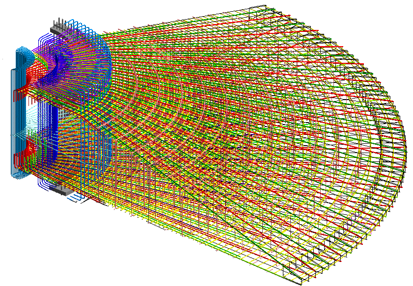
3D of one of the symmetrical quadrants
To finish the job, and provide good use of the rebar tool, the visibility options must be made and modified. By default, it should be noted that reinforcements are only visible in the views that are modeled, to avoid excessive weight of the model. For this reason, specific 3D views have been created to add specific filters and options. In general, in this case, we worked with bar numbering, using a specific parameter that affected the structural rebar to be able to filter.
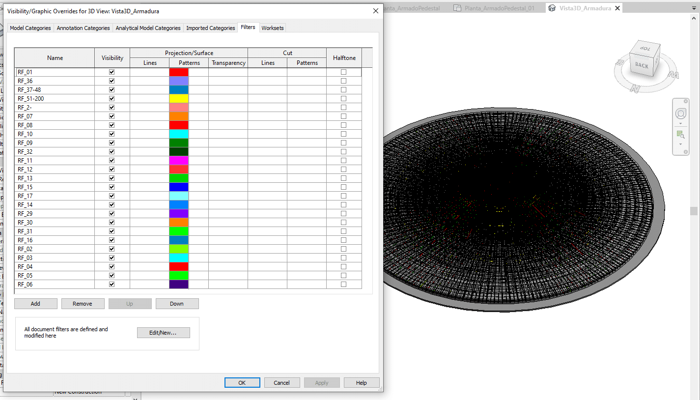
3D and filters generated by numbering type
In subsequent posts, we will continue explaining the process, indicating how a Dynamo definition has been generated for the automatic modification of dimensions from Excel.
If you have any questions, do not hesitate to contact us: info@atbim.es
By Andrea Gracia, BIM Coordinator at ATBIM.